How I Built a 3D Impression Toy in WebGL
Here’s a demo.
Here’s the source code.
This post assumes some familiarlity with graphics programming, namely coordinate systems, and shaders. It is not my intention to exclude potentially interested readers. If you’d like a good resource that covers a lot of the requisite concepts, here’s an awesome reference.
Background
Recently, I built a 3D impression toy to improve my skills as a graphics programmer. I’ve been working hard to level up my graphics programming kung foo by reading a ton online, and following various tutorials, but it was time to dive in, and try something on my own.
What’s a 3D impression toy? Remember these?
Why build one?
- They’re cool.
- It’s a finishable project. It’s small enough to let me focus on concepts I want to master. It’s challenging enough to make me think and not be bored.
How did I do it?
I broke the problem down into these parts:
- Basic scene setup
- Scaling the model to fit in a unit volume (1x1x1)
- Dividing the xz plane into cells based on some resolution
- Drawing columns in each of the cells
- Only drawing the columns up to the height where it pokes through the top of the model
Basic Scene Setup
To get a basic scene up and running, I need a model to render, and a some way to render it.
For a model, I use the Stanford bunny, mostly out of convenience, since it exists as an npm module. My implementation allows for any arbitrary model to be used, but I only make use of the bunny for now.
For drawing, I use the the wonderful regl project to interact with WebGL. Rather than interacting with WebGL state directly in a super side-effecty way, state changes are managed by regl via a nice declaritive API.
There are no surprises getting this part set up. Here are the highlights:
- Load the bunny’s vertex and edge data
- Create a world space transform for the bunny
- Calculate a model matrix using the transform and pass it to the WebGL context via regl
- Use regl-camera to magically create and pass the projection and view matrices to the WebGL context. (3rd party libraries are good when I’m in a 3D Impression toy making hurry!)
- Apply the projection, view, and model matrices to draw the bunny in clip space.
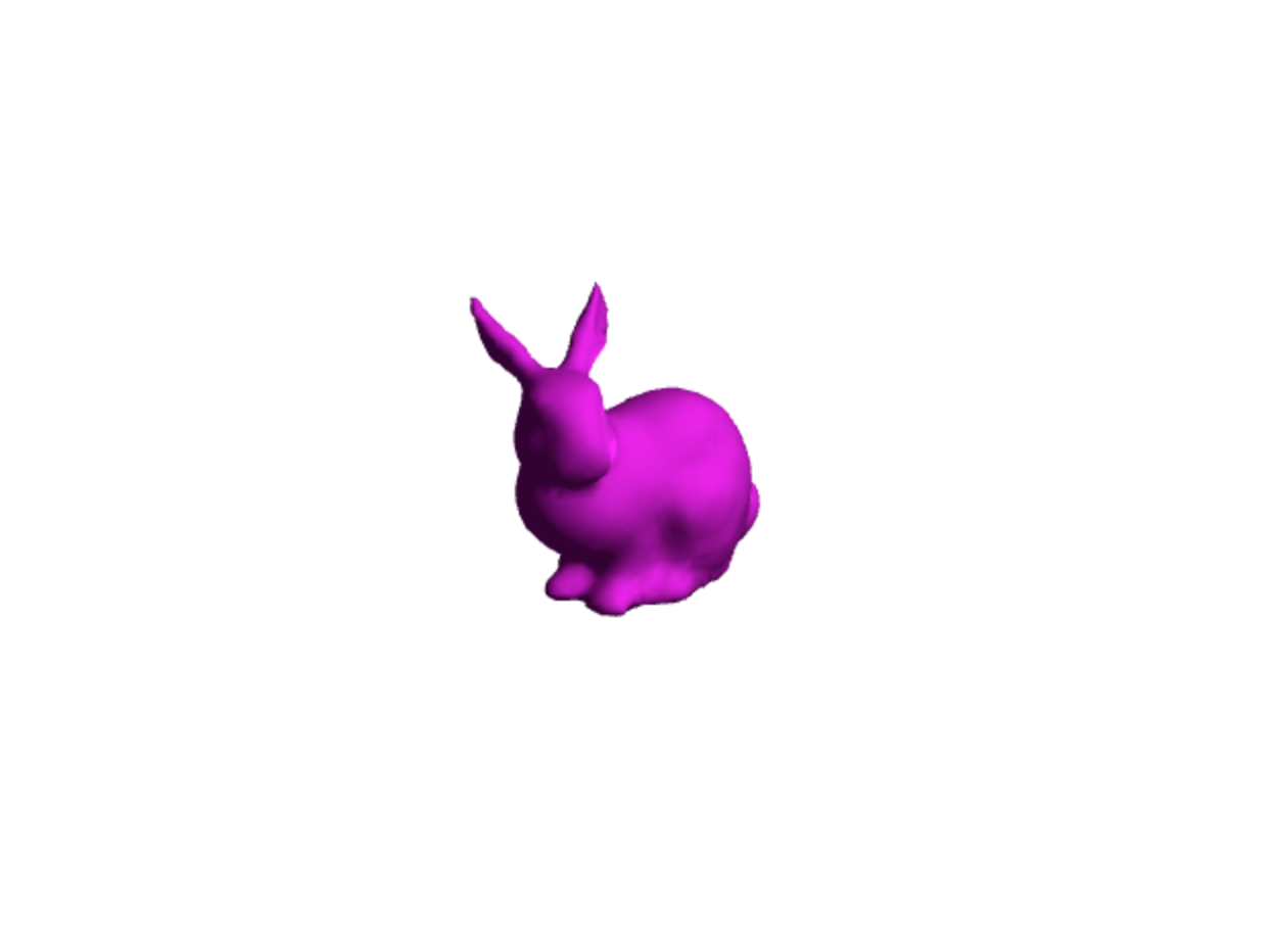
I add some lighting in the fragment shader for realism, and here’s my progress so far:
Scaling the model to fit in a unit volume
For simplicity (and sanity) in the following steps, I want scale in world space to be universally the same for any 3rd party model. In other words, I want scale in model space to equal 1. This was accomplished by taking every single vertex of the model and dividing each x, y, and z component by the largest x, y, or z.
e.g.:
function normalizeVertices(vertices: number[][]) {
  const max: number = _.max(_.flattenDeep(vertices));
  return vertices.map(pos => pos.map(n => n / max));
}

console.log(normalizeVertices([[1, 2, 3], [0, 5, 0], [2, 0, 8]]));
// [[.125, .25, .375], [0, .625, 0], [.25, 0, 1]]
Divide the xz plane into cells
A column moves along the y axis, so a column’s position and dimensions are considered in x and z.
Most 3D impression toys have their columns placed in a hexagonal arrangement. For simplicity, I make a grid of square cells that is the same number of cells wide as it is deep.
My goal here is to write a function that returns an array of world space transforms, each representing the position and dimensions of a column that will eventually be drawn.
Important considerations:
- I want to be able to change the cell density of the grid, so the desired cell amount is parameterized.
- Naively, the first cell will be placed at (x = 0, z = 0) and subsequent cells will be placed in the positive x and z directions. Instead, cell positions need to be offset so that the center of the grid is at (x = 0, z = 0).
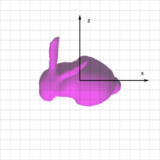
Here’s an illustration of the grid and bunny in world space to show what the heck I’m talking about.
Drawing columns in each cell
Now I start drawing columns!
For a model, I use a cube whose world space y scale has been set to 1, the height of the unit volume.
The cells I defined in the previous step tell me the position and dimensions for each column to be drawn, so I loop over the cells and do a draw call for each one. I also go back and add a little bit of spacing between cell positions for some extra realism.
At this point, I use a separate vertex and fragment shader for the column, since I’ll be writing some very column-specific shader code in the next step.
This gets me to here:
Only drawing columns up to where they intersect the surface of the model
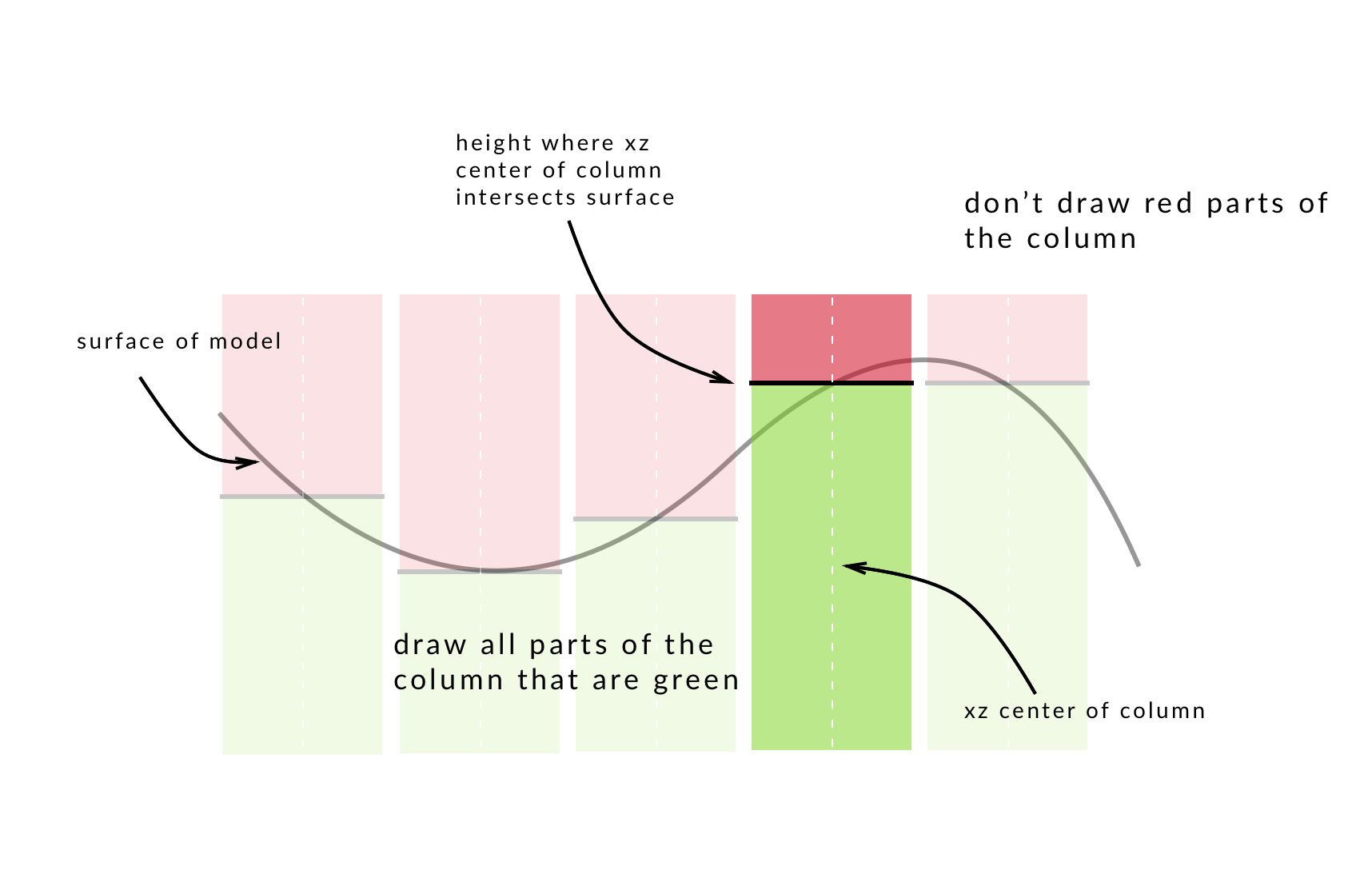
This part is where the real magic happens. A fragment of the column should only be drawn if that fragment’s height in world space is below where the xz center of the column makes its final intersection with the surface of the model. That’s a mouthful. Here’s a picture to show what I mean:
So in the column’s fragment shader, this is what I’m aiming for:
if (thisFragmentHeight <= heightWhereColumnPokesThroughShape) {
  alpha = 1.0; // shade this fragment
} else {
  alpha = 0.0; // don't shade this fragment
}
Figuring out the fragment’s height comes easily, since if I define a varying variable in the vertex shader, it’s value will be interpolated for each fragment and accessable to us in the fragment shader.
Now what about the height where the column pokes throught the shape? There’s a problem with our approach so far. In world space, finding the height where the column pokes through the model is kind of a nightmare. For each of the model’s position vertices, I need to see if it’s contained within our column, and if it is, I need to see if there is a position vertex above it, within the xz bounds of the column. When there’s no vertex above, the column pokes through. Besides the exponential complexity, I’d need to pack the entire model’s position coordinates in a texture and send it to the fragment shader to have these variables in scope to do the calculation.
Yuck.
Making a depth map
An alternative approach is to make a depth map of the bunny from a bird’s eye view. I’ll refer to this bird’s eye view as depth space, and it’s the primary coordinate system I’ll be working in intead of world space, because it’s the perspective used to make the depth map.
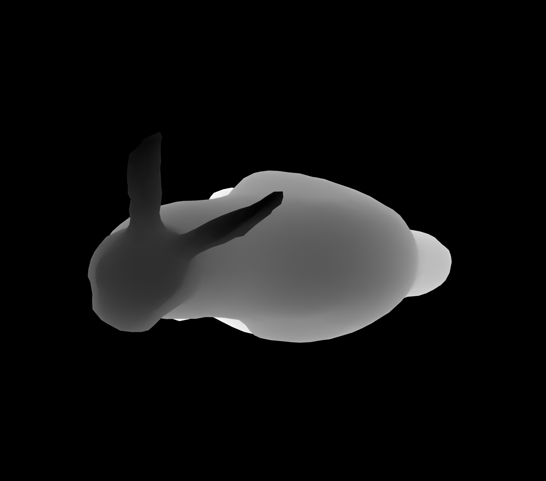
A depth map encodes distances from the viewer as greyscale color, so something really far away, at a distance of 1.0 appears as white, while something really close, at a distance of 0.0, appears as black. So, I create a depth map of the bunny in depth space, and when I want to know the distance from the depth map camera to the surface at a specific position, I can sample the color of the depth map at that position. Because distance is encoded as greyscale color, the sampled color’s blue component is z.
Here’s a depth map of the bunny:
In the column’s fragment shader, I can sample the depth map at the column’s xz center and test whether or not the sampled value is larger or smaller than the fragment’s depth.
Remember, I’m working in depth space now, so you can think of a fragment’s depth as it’s distance from the depth map camera (the bird’s eye view from which the depth map was created).
Here’s an illustration showing the difference between considering heights in world space and depths in depth space.
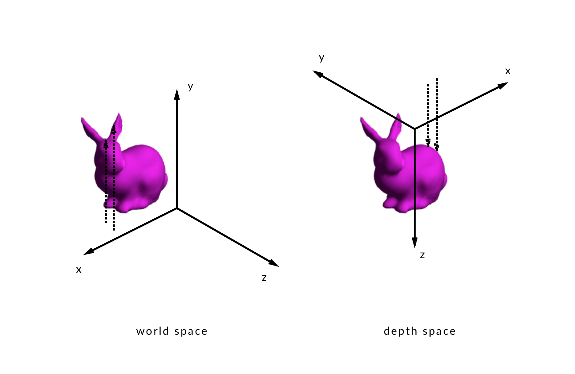
Similarly, the depth encoded in the depth map is also a distance from the depth map camera, so the annoyingly complicated world space problem described earlier turns in to the shockingly simple depth space solution:
if (fragmentDepth > surfaceDepth) {
  alpha = 1.0;
} else {
  alpha = 0.0;
}
When the fragment’s depth is farther away from the depth map camera than the surface, the column hasn’t poked through yet, so it’s alpha should be 1.0.
Conversely, when the fragments’s depth is closer to the camera, than the fragment’s depth, the column has poked through, and that fragment of the column should have its alpha set to 0.0.